 |
 * * |
 |
| north pitney |
t h e M a z e |
|
* |
|
|
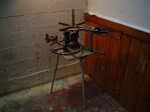
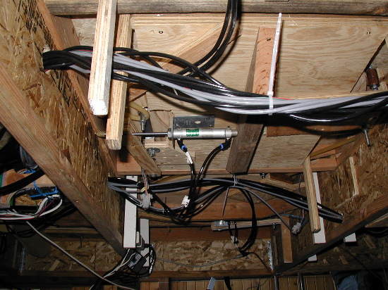
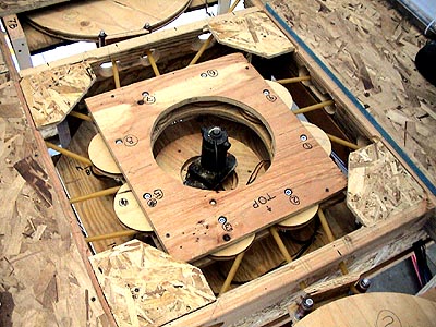
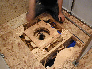
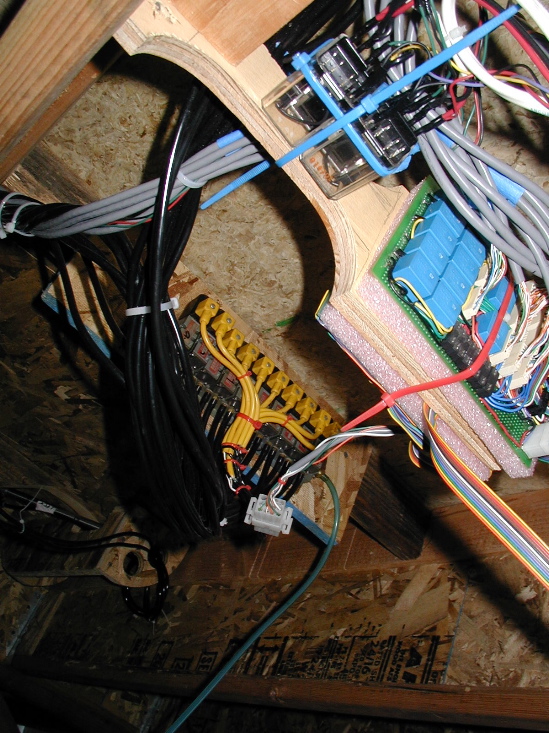
This is the central mechanism for getting power to the 8 panels that can rotate in any direction. The left hand image is the old setup when the entire maze was powered with a single DC motor. The power was delivered to the appropriate door via a small electric clutch and then out through the belt (made of surgical tubing) to the door. This system was elegant but failed because the clutches were to worn to reliably move the doors quickly. This is the risk of engineering surplus components into a system. Below is the modified power center. It has 8 separate motors (one for each door) mounted where the bad clutches once were. The Teleo modules that run the motors can be seen around the inside of the round opening in the center.
|
 |
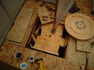
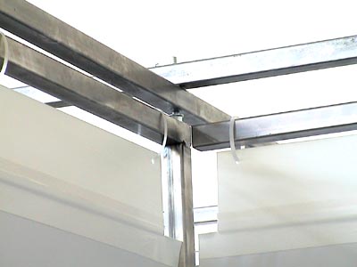
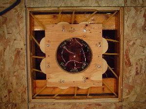
These photos are details of the door mechanisms. The top left is a proto type made out of welded square steel tubing. | 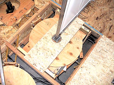 |
I learned that welding is not the best way to mount bearings and achieve exact clearances and tolerances I then turned to a more familiar medium in wood. While it did not offer much precision, the quick production of experimental prototypes allowed for rapid improvement in design. Originally, the position sensing was done with 4 limit switches that were part of the pneumatic circuit so that the pneumatic relay would lose power when the appropriate limit tripped. I learned that tiny limit switches get ground into junk pretty easily when they are run against rough plywood discs for hours upon hours. |
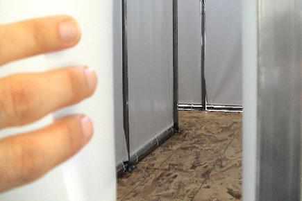
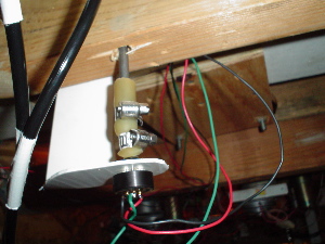
The final door mechanism consists of a large (24" X 1 1/8") plywood pulley mounted on a lazy susan with a spring activated locking bearing that runs in a grove on the pulley face. A pneumatic releases the lock so that the pulley can rotate. When the door nears it's destination, the pneumatic releases the lock which then springs into the next slot that comes around, thereby stopping the door at precisely one of four positions. I replaced the limit switches with a potentiometer (image at lower left). This allowed the machine to deduce a position from the percentage of resistance in the pot. The pot value was read through the Teleo Motor Controller module by the computer. |
|
 |
 |
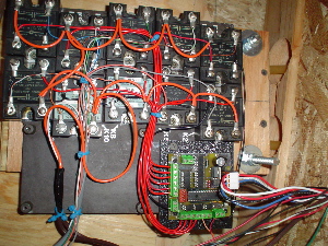 |
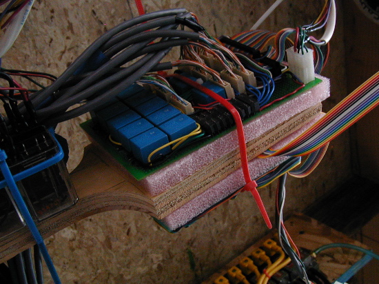
This
is a shot of the ten 110ac relays run by the Teleo
Digital Out module. All of the pneumatics are run by this board.
|
 % % |
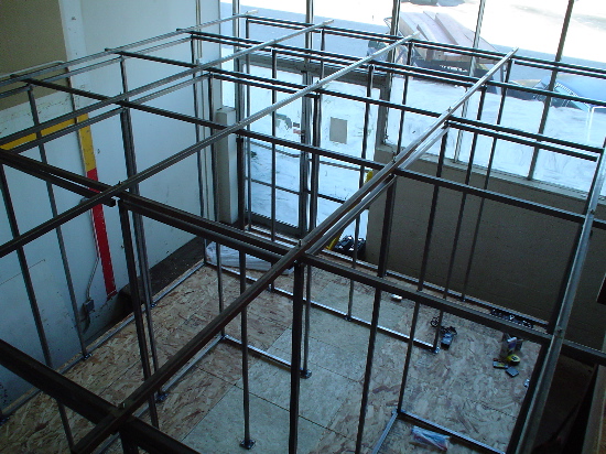 % % |
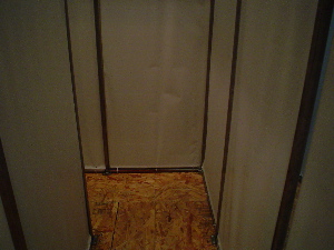
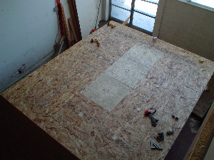
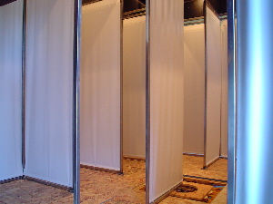
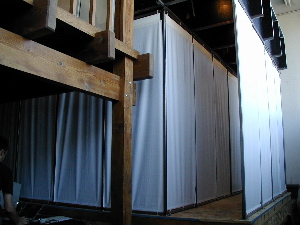
Installation
in the Berkeley space.
|
|
|
 ^ ^ |
The
images above show some details of the first I/O boards that I built
myself. Originally the maze was activated by sending the board (lower
left, with the massive bundle of gray wires coming out of it) a 6
bit binary number. It would then activate one of the sixty four circuits
that would
start a particular door moving to a particular position. This system
worked well for a time but when trouble arose it was impossible to
trouble shoot. I thought I was being clever by jamming things as
tightly as possible onto the proto boards. NOT!
|
|
 #
#
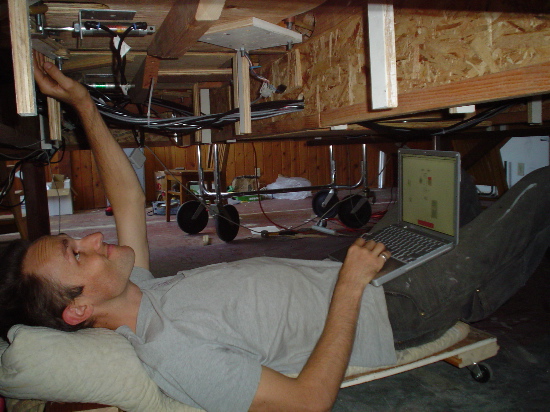
Me trouble shooting.
 |
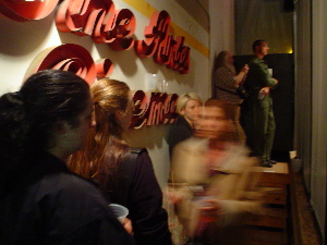 |
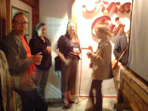
Opening
night waiting in line to experience the maze.
|
|
 |
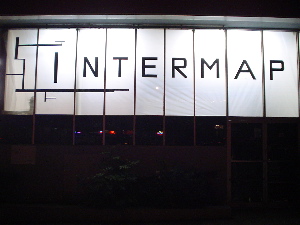 |
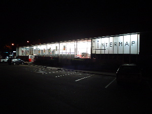
The
view from the street of the gallery space.
|
|
 * * |
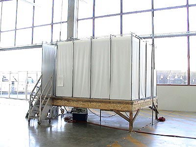 * * |
| These photos are from the commencement show at CCAC. It was a beautiful space for the installation with it's high ceilings and ample floor space. The flood of light from the wall of windows had the drawback of providing a reference at all times so it was difficult to get turned around or disoriented in the maze. | |
|
This
is a still from an earlier tracking patch wherein I had 2 cameras.
I had to toggle between views so this image only shows half the maze.
|
The Quicktime movie
on the left represents the pixels that my Max
/ Jitter patch has tagged as having movement. The image on the
right is a composite of the source video, white graphics representing
the currant door position and black squares representing which triggers
are being tripped by the motion.
|
|
The Flash game
below has no goal other than to facilitate your conception of the space
created by the maze. In the installation, I used this to animate the
persons movement within the maze in real time. This provided an additional
way for people outside the maze to engage the piece without making the
person inside feel like they were on camera. It is important to me that
the participant have a private experience in the maze so they can relax
and focus on their interaction with it. That can be hard to do if you
are on CCTV. |
Photos by: |
*David
Williams
|
^
Max Morales
|
#
Mary Wilson
|
%
North
|
 ^
^ ^
^ %
%